
Technical Insights
Functionally Testing a DDR5 DIMM Is Not Difficult, but It Is Complicated!
![]() 10 min
10 min
![]() 8 min
8 min

PCI Express is one of the oldest SerDes standards in the world, and it has been instrumental in advancing the computer architecture of laptops, personal computers, servers, and even older mainframe computers. A true stalwart of the “computer” industry, PCI Express has evolved dramatically over the last few decades, and it is now continuing to find use in fascinating applications such as volatile and non-volatile memories. Read on to learn how Introspect Technology serves the physical-layer margin verification requirements of PCI Express endpoints. Whether you are an IP maker, a chip maker, or a module or system maker, you will certainly find great joy in rapidly verifying whether your transmitters and receivers are properly constructed and connected.
Different Introspect Technology products can be used for PCI Express testing. For example, the figure below shows the SV1C-12 system, which is an 8-lane 12.5 Gbps system that is ideal for Gen3 testing. Alternatively, the SV7C-17 is ideal for x16 Gen4 testing, and the SV2C-32 is ideal for x8 Gen5 testing. Oh, and did we mention the SV2C-PAM4 does 64 Gbps BER testing on Gen6?
The hardware setup in Figure 1 is one of the many reasons the Introspect tools are so appealing. On the right hand side, you see a single “BERT” system that has the reference clock injection source, the pattern generators, and the pattern receivers. It even has auxiliary IO signals for controlling things like device reset signals. With this all-in-one architecture, the problem of verifying transmitter and receiver margin on your PCI Express link becomes more of a software or automation problem and not a hardware issue, and this will be described in later sections of this article.
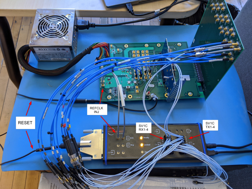
Figure 1: Simple hardware setup for testing any PCI Express link
The next figure shows how the power is typically connected on a Compliance Base Board, and the one after shows how a reset signal can be added.
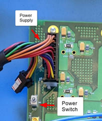
Figure 2: Illustration of the power connection
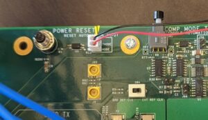
Figure 3: Illustration of the reset signal connection
As mentioned, software automation is another major benefit of using the Introspect tools for PCI Express link verification. These tools are all operated on the award-winning Pinetree software, which is a Python-based automation environment. Within a Python framework, you can select the data rates that you want to test at, and you can even customize what the PCIe rates are. For example, the following illustration shows setting the Gen3 data rate to be exactly 8 Gbps.
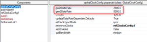
Figure 4: Setting the Gen3 data rate at 8 Gbps
Similarly, Figure 5 shows that different testing options can be configured using attributes of the Python component classes in the software. Here, we are electing to automatically reset the DUT, which means that we are taking advantage of the hardware reset connection in Figure 3 above.
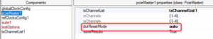
Figure 5: Screenshot indicating how to automatically reset the device under test
Pinetree also has pre-built functions for PCI Express transmitter signal integrity testing and receiver sensitivity testing. For example, Figure 6 shows a user interface that provides options for different tests to be executed. Simply selecting True on a test like the gen3SjTolTest would enable the tool to automatically train a PCI Express endpoint and then perform the jitter tolerance testing on it.
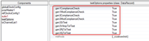
Figure 6: Available options for the tests to perform
The following sections show some quick examples of the test reports that are generated by the Introspect PCI Express tools. We first show the basic pattern checks to ensure that the link is up. Then we show real device performance characterization.
Upon power-up, a PCI Express compliant device will identify the active lanes by detecting the load impedance at the receivers and begin transmitting TS1 Ordered Sets on those lanes. If the device does not receive at least 8 consecutive training sequences within 24ms from lane detection, it will begin transmitting a Compliance Pattern on all active lanes. In this test, we determine if the DUT can operate at Gen1 rate (2.5 Gbps) and what lanes have a responsive transmitter and receiver by detecting the transmitted Compliance Pattern.
Starting 'testCase_gen1ComplianceCheck'

TestCase: Gen 1 Compliance Pattern Check

Starting Compliance Pattern Check

Pattern detection successful on channels [1, 2, 3, 4]

Length of detected compliance pattern (in 10 bit symbols):

[64, 64, 64, 64]

Number of loops locked:

[3405807, 3405806, 3405807, 3405907]

Finished 'testCase_gen1ComplianceCheck'
After identifying the active lanes, a PCI Express device will begin transmitting TS1 Ordered Sets and monitoring its receivers for TS1 Ordered Sets from other devices. Upon reception of at least 8 TS1s, the device will inspect the advertised Data Rate Identifier and the Compliance Receive bit. If the Compliance Receive bit is asserted, the device will move to the maximum rate supported by both itself and the received TS1 and begin transmitting and monitoring the Modified Compliance Pattern. The contents of the error status of the transmitted pattern is determined by whether the device successfully detected the incoming Modified Compliance Pattern. In the following log, we determine if the DUT can operate at Gen1 rate (2.5 Gbps) and successfully receive a Modified Compliance pattern on all the active lanes.
Starting 'testCase_gen1ModComplianceCheck'

TestCase: Gen 1 Modified Compliance Pattern Check

Starting TX ChannelList setup

txChannelList1: Channels 1-4 are linked due to the PatGenController for PatternTimelines

Starting Modified Compliance Pattern Check

Pattern detection successful on channels [1, 2, 3, 4]

Error Status Bytes:

[0, 0, 0, 0]

Length of detected compliance pattern (in 10 bit symbols):

[128, 128, 128, 128]

Number of loops locked:

[13, 123, 3123204, 3119793]

Training Sequence Symbols 1-15:

Channel 1: F7 F7 FF 1E 00 00 4A 4A 4A 4A 4A 4A 4A 4A 4A

Channel 2: F7 F7 FF 1E 00 00 4A 4A 4A 4A 4A 4A 4A 4A 4A

Channel 3: F7 F7 FF 1E 00 00 4A 4A 4A 4A 4A 4A 4A 4A 4A

Channel 4: F7 F7 FF 1E 00 00 4A 4A 4A 4A 4A 4A 4A 4A 4A

Finished 'testCase_gen1ModComplianceCheck'
After identifying the active lanes and failing to receive TS1 Ordered Sets, we proceed to more advanced signal integrity testing. For example, all transmitter presets are tested through the appropriate automation procedure which is built into the Introspect tool. The following graph shows a transmitter bathtub plot on 4 active lanes. This bathtub plot was acquired simultaneously on all lanes.
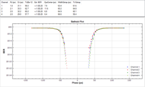
Figure 7: Transmitter horizontal eye opening test (bathtub plot) on 4 lanes simultaneously
Similarly, full eye diagram tests are obtained, an example of which is shown in Figure 8. These eye diagrams are true BER-based eye diagrams, which means that they represent statistically deep measurements. For example, the eye diagram shown below was captured with a 1e-6 error probability setting.
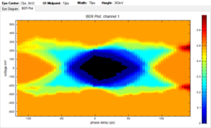
Figure 8: Eye diagram result, captured on 4 lanes simultaneously
Finally, preset measurements such as overshoot can be made using the analog capture tool. In Figure 9, we show how the analog capture tool provides an oscilloscope waveform that is averaged and analyzed to extract measurements such as voltage swing and preset overshoot.
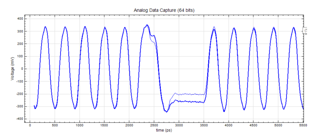
Figure 9: Analog capture result – a comparison of the analog waveforms for TxPreset0 and TxPreset1 on CH1
Now, we look at the impairment capability of the Introspect tools that are used to measure the DUT’s tolerance to various analog characteristics. Figure 10 shows the jitter tolerance graph that was automatically constructed using the PCI Express tools in the software. Note that an individual plot is generated for each channel in the PCI Express link, and these measurements are obtained simultaneously.
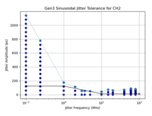
Figure 10: Receiver sinusoidal jitter tolerance test results
Finally, the following figure shows the receiver voltage sensitivity test on a real PCI Express receiver. The graph shows the error count on the receiver as a function of programmed voltage swing.
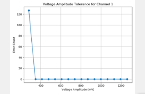
Figure 11: Receiver voltage sensitivity test report
In this article, we described how the Introspect Technology C Series Personalized SerDes Testers can be used to rapidly verify the signal integrity on your PCI Express links. This is important because it can help you save days of debugging random and intermittent behaviors at the system level. If you know that the signal integrity is solid, you can focus on other sources of intermittency such as state machine instability or software bugs.
For any inquiries, please reach out to the Introspect team by sending an email at info@introspect.ca


