
Technical Insights
5 Things You Need to Know About the PurVue Analyzer® Embedded Real-Time Oscilloscope
![]() 4 min
4 min
![]() 8 min
8 min


To enable the multiple waves of innovation in the world today, semiconductor devices continue to integrate more connectivity features than ever in the past. Modern image sensors, radar sensors, displays, microcontrollers, and edge processors all incorporate sophisticated packet-based communications protocols that are often more advanced than network protocols that were previously only used in mainframe computers. These new component-level protocols require extensive testing for the purpose of design validation, and this testing can no longer be accomplished by simple oscilloscope setups. Deep data analysis needs to occur using tools such as protocol analyzers and exercisers.
In this blog, we introduce the architecture of an oscilloscope, the architecture of a protocol analyzer, and the strengths and weaknesses of each kind of measurement instrument. We do so by showing real-life measurement examples as well as measurement insights that we have gained through the years. But first, let us learn how an oscilloscope is built!
Figure 1 shows a high level block diagram of an oscilloscope. As can be seen, the most important component in an oscilloscope design is the Analog to Digital Converter (ADC). This is the component that digitizes the input signal (usually a voltage signal) and converts it to numerical values. The ADC is a high-resolution component that generates a lot of data for each input sample. For example, in a 12-bit 20 GHz oscilloscope, each sample being measured produces 12 bits of data that needs to be processed before being displayed. For this reason, an oscilloscope typically has two memory spaces, one for storing the raw digitized numbers and the other for storing the final waveform data in numerical format after it has been processed.
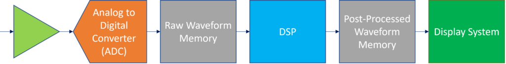
Figure 1: Architecture of an oscilloscope
Figure 2 shows the block diagram of a modern protocol analyzer. As can be seen, the processing chain is a lot shorter than that of an oscilloscope, and this is the most critical differentiation between the two instrument types. In the protocol analyzer, there is no ADC, and digital data is processed directly in a hardware state machine.
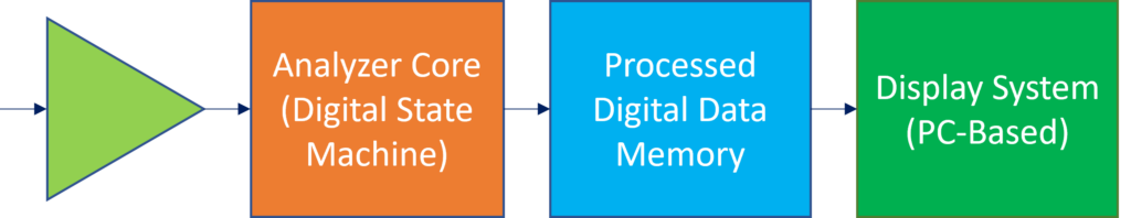
Figure 2: Protocol analyzer block diagram
From the above block diagrams, the difference in application between an oscilloscope and a protocol analyzer becomes evident. In short, an oscilloscope is ideal for measuring waveforms, whereas a protocol analyzer is ideal for measuring data. With the importance of data in today’s machine learning and environment sensing applications, the ability to “measure” data is paramount, and this is why protocol analyzers are becoming indispensable in modern-day validation and characterization laboratories.
Figure 3 summarizes the different measurements offered by the two instrument types. As can be seen, an oscilloscope provides insight into the shapes of voltage signals being measured. The shape of a signal helps quantify parameters such as signal rise time, noise, and jitter. And these parameters are used to estimate the quality of the communication link from a physical standpoint. On the other hand, the protocol analyzer provides deep insights into the data being transmitted. Every bit of every packet is detected and verified, and this is useful in ensuring data integrity as well as ensuring compliance to the very complicated protocol specifications.
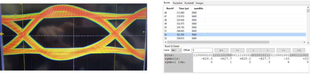
Figure 3: Typical (a) oscilloscope measurement, (b) protocol analyzer measurement
When it comes to validating complex packet-based protocol implementations, the most serious limitation of the oscilloscope is the existence of exorbitantly large measurement gaps that are due to the limited acquisition memory and the slow trigger circuitry. Even the most expensive real-time oscilloscopes today suffer from gaps that render them incapable of measuring even 10 milliseconds worth of data – a very short time duration. To illustrate this, refer to Figure 4, which is drawn to scale based on the published specifications of a typical expensive real-time oscilloscope. In this figure, a long protocol packet transmission is being measured, and it is signified by the thick red line at the bottom of the figure. If an oscilloscope is trying to capture this packet communication, it would trigger at the left hand side and store up to, say, 0.5 milliseconds worth of data. Then, the oscilloscope goes through an intensive processing step before displaying the waveform on its screen. This processing step is so intensive that it can last for 1 second before the next “waveform” can be displayed, and the scale in Figure 4 illustrates this. Namely, each screen in the figure represents 5 milliseconds worth of signal waveform, and the gap between the two screens is 1 second. Practically, the processing time in typical oscilloscopes can be even much longer than 1 second, and the capture duration can be less than 5 milliseconds.
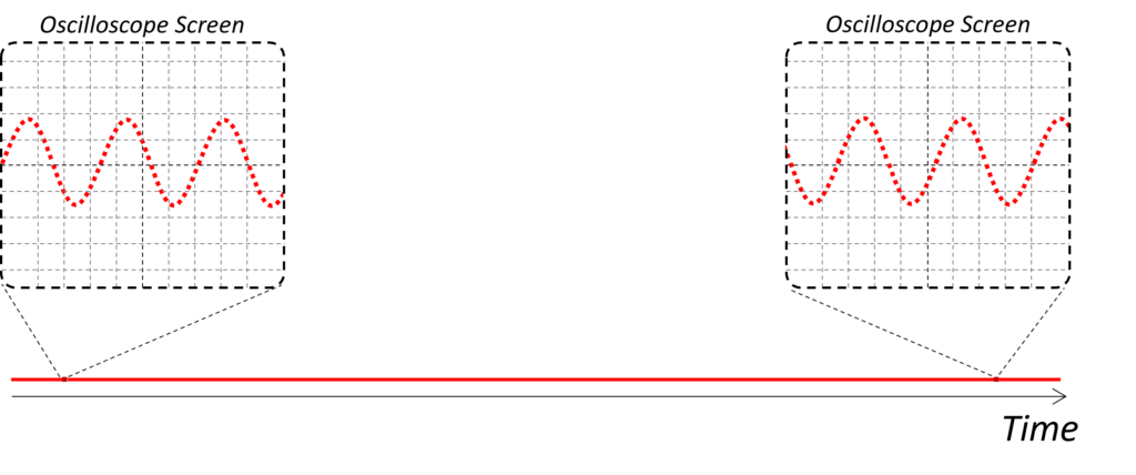
Figure 4: Sampling gap in an oscilloscope
If a bit error occurs anywhere in the gap shown above in Figure 4, then the oscilloscope will never be able to catch it. In fact, this notion of finding the root cause of bit errors is the primary reason we authored this blog. Oftentimes, engineers would say that the “eye diagram looks clean”, and a real-life example of such eye diagram is shown in Figure 5. In this figure, a device eye diagram was measured using an oscilloscope and confirmed to be “clean”. However, the device had a timing fault that resulted in rare errors, and these errors were manifesting themselves as protocol communications failures. They were never detected except when a protocol analyzer from Introspect Technology was introduced.
The reason the protocol analyzer was able to diagnose the errors in the above device is shown in Figure 6. In the figure, the same signal of Figure 5 is measured using a protocol analyzer, and you can see that the protocol analyzer is able to capture the entire 1 second duration of data without interruption. This continuous, uninterrupted measurement is what makes the protocol analyzer ideal for measuring links based on complex packet-based communication protocols.
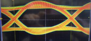
Figure 5: Real example of a clean eye diagram
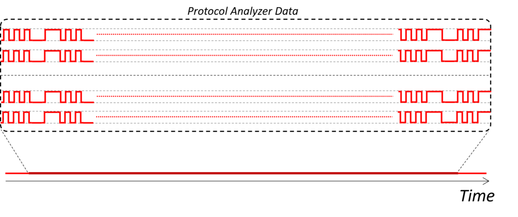
Figure 6: No sampling gap in a protocol analyzer
Referring to the same device that was measured in Figure 5, the following figure shows the rare errors that were diagnosed using the Introspect Technology protocol analyzer. As can be seen, it can take several milliseconds before an error occurs. The main job of the protocol analyzer is to provide a complete time-record of all data being measured and to assist in diagnosing the errors, which could be logical ones and not necessarily analog ones.
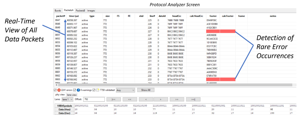
Figure 7: Protocol analyzer trace showing rare errors
Another limitation of using oscilloscopes to validate protocol-based systems is the limited number of channels. ADC circuits in an oscilloscope are very complicated, so it is not practical to integrate many of them in a single oscilloscope. As such, oscilloscopes typically offer only four channels, and this number is divided by two if the signals being measured are differential. Clearly, if an image sensor uses 16 differential lanes, the oscilloscope would not be a very practical solution for validating it. On the other hand, protocol analyzers typically support a much larger number of channels.
Finally, the sampling technology in an oscilloscope is expensive, and the cost keeps increasing as oscilloscope bandwidths increase. It is not unheard of to spend $0.5M on a state-of-the-art oscilloscope. While such investment is definitely worth it for certain characterization and measurement applications, it becomes impractical for validating or functionally testing completely assembled systems.
Before closing this blog, we would like to note that some protocol analyzers are still able to measure waveforms. These analyzers would not possess the flexibility nor the analog performance of a real-time oscilloscope in general. However, they can be used in-situ to diagnose some waveform issues. For example, Introspect Technology analyzers are usually able to provide eye diagram measurements, an example of which is shown in Figure 8.
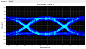
Figure 8: Eye diagram from Introspect Technology analyzers
In this blog, we addressed a common question we receive, which is whether an oscilloscope is a more useful tool for validating digital protocols or a protocol analyzer. To address this question, we introduced the architecture of the oscilloscope and that of the protocol analyzer, and we highlighted some of the limitations of using an oscilloscope for complex protocol validation. We illustrated how the sampling gaps in oscilloscopes are detrimental in diagnosing rare protocol errors.
