Industry Challenges
Have You Heard of C-PHY 3.0?
![]() 4 min
4 min
![]() 6 min
6 min


A high-speed electrical receiver’s basic operation is to capture data from a transmission device. This entails being able to accurately decode a stream of bits and distinguish between a 0 and 1. However, as a result of distortions in the signal path due to noise and cross-talk, the actual signal received may be impaired and a receiver might not be able to correctly interpret the data. Well designed receivers thus need to be tested systematically with stressed signals in order to ensure sound operation and high product quality.
Design engineers need to account for the effects of signal degradation along the transmission path in a real system when developing their high-speed receiver circuit. In a real system implementation like a gaming laptop or high-end computer, a large signal from a transmitter can shrink by 10-50 times by the time it reaches the receiver. Receiver stressed eye testing entails mimicking the degradation effects on the signal – in a controlled laboratory environment – and verifying if the receiver can still function despite a poor signal quality.
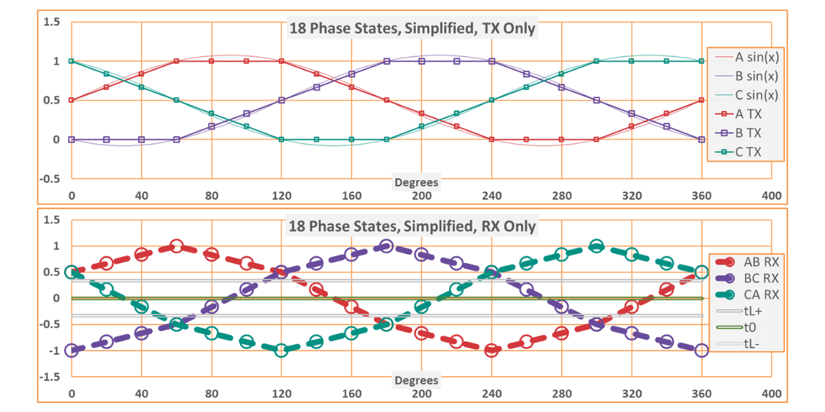
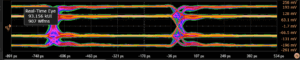
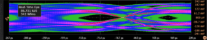
An eye diagram is a graphical representation of the signal integrity and is constructed by overlaying the rising and falling edges of all bits in a data stream. Under nominal conditions with good signal quality, the eye width and height are expected to be wide open as shown in Figure 1 (a). (Can you guess why there are four levels in this eye diagram? See our blog about C-PHY 3.0). However, for a signal with poor quality, the eye is closed as seen in Figure 1 (b). Despite such degraded operating conditions, the receiver must still decode the correct 0 and 1 bit data.
(a)
(b)
Following are some of the common methods of creating stressed eye diagrams that mimic a distorted signal:
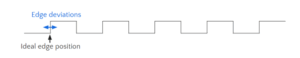
Jitter is an impairment in the signal which arises due to the edges of the datastream moving away from their ideal positions. As seen in Figure 2, when the rising and falling edge positions are not steady and deviate, they impact the receiver’s ability to correctly interpret the bitstream.
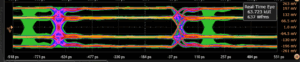
The tolerance of a receiver to this distortion can be determined by injecting sinusoidal jitter in the signal. By varying the jitter frequency and amplitude, the eye diagram can be closed and the response of the device under test can be determined. The impact of injecting jitter on the eye diagram can be seen in Figure 3:
(a)
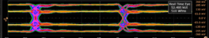
(b)
(c)
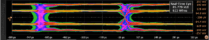
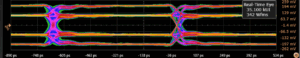
Duty cycle distortion (DCD) refers to the noise arising due to the systematic difference in the duration of the high pulse in comparison to the low pulse of the signal. In the ideal setting, both the high and low sections of the waveform should be equal. However, defects in the PLL circuit design or signal path can create unequal pulse widths. Adding DCD creates an asymmetry in the eye and closes it along the time axis in a manner that is very similar to how real systems behave. DCD injection is shown in Figure 4.
(a)
(b)
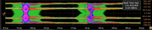
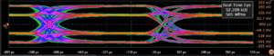
Another common technique for stressing the eye is by injecting ISI through bandwidth reduction. When a channel has limited bandwidth (i.e. it only allows for certain frequencies), the transmitted signal gets spread out and one symbol can start interfering with the subsequent one. The resulting bit transitions are slower and the edges of the pulses are not as sharp, thus resulting in a more stressed eye. Figure 5 shows the impact of bandwidth reduction on signal integrity.
(a)
(b)
So how does one determine how much impairment a receiver should be able to tolerate? This is where standards come in and define the requirements for receiver testing. Various industry standards define the voltage level thresholds (for the vertical boundaries) and the timing requirements (for the horizontal boundaries) of the eye diagram. The idea is that these standards define the width/height of the stressed eye that represents the worst operating condition the receiver is expected to perform under. If the device functions with such a signal, it is considered to be conformant with the specification.
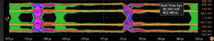
As an example, the MIPI C-PHY specification requires that a conformant device should be able to successfully operate with an eye width/height of 0.5 UI/80 mV. Introspect’s SV5C-CPTX MIPI C-PHY Generator, in combination with the Pinetree software, is well equipped to produce such a stressed eye for receiver testing. Our custom algorithms dynamically vary parameters such as jitter, DCD and noise amplitude based on the user’s test setup to achieve the optimal combination needed for a stress test.
A video showing the dynamic variation of the injection parameters using Introspect’s Conformance Test Suite (CTS) package is shown below.
As can be seen, the software is testing different parameters to stress the eye and finally settles on the values that yield the desired eye width/height of 0.5 UI/80 mV. The final stressed eye for conformance testing is shown in Figure 6.

Conclusion
Receiver stressed eye testing is a critical component of the design validation phase for any interface. Introspect’s pattern and signal generation hardware, coupled with state-of-the art Pinetree software, offers engineers a seamless way to characterize and ensure compliance of their receivers. If you’d like more information on our solution offerings, send us an email at info@introspect.ca.
