
Technical Insights
5 Things You Need to Know About the PurVue Analyzer® Embedded Real-Time Oscilloscope
![]() 4 min
4 min
![]() 6 min
6 min

The Management Component Transport Protocol (MCTP) specification, which is published by the DMTF standards organization, is integral to many computer and server architectures because it defines how a system management controller can communicate with managed devices such as PCIe add-in cards and disk drives.
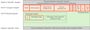
The MCTP protocol is a byte-aligned messaging system that rides on top of an existing physical layer and/or communications protocol. This is why it is referred to as a transport layer – it only defines the bytes constituting a (management and control) message, and it does not define the way the bytes are transmitted. This concept is illustrated visually in Figure 1.
The grey sections are the typical header and footer sections of an underlying physical layer such as PCI Express (PCIe). The orange and green sections are the payload bytes defined by MCTP. To the underlying physical layer, the MCTP packets are just payload bytes, and they follow the same encoding and mapping schemes of the physical layer.
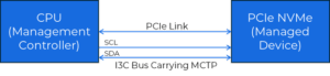
To explain this further, imagine a system motherboard containing a solid-state disk (SSD) drive that is connected through a PCIe slot. The SSD is a managed device in the context of MCTP. And MCTP control messages can be transported between the CPU and the SSD over the PCIe protocol itself. This is illustrated schematically in Figure 2.

Now, if you have ever used PCIe, you will know that this is a very high performance, high complexity bus, so it is better to use it for executing real mission-mode transfers (like reading large files from the SSD drive) at maximum speed, instead of using it for system management. This is why in many practical implementations, the MCTP protocol often rides on other simpler physical layers such as the SMBus or I2C. And now with the recent I3C binding, the MCTP protocol happily rides on an I3C physical layer! See Figure 3.
All MCTP packet transactions in this case take the form of SMBus write transactions in order to send request or response messages between devices. Hence, each device on the bus (even the controller) shall have an address to be the target of the transaction.
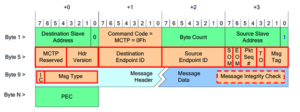
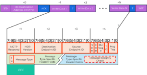
Figure 4 shows the MCTP packet format over SMBus/I2C with the addition of four bytes (byte 1 to byte 4) defining the medium-specific header. The byte 1 to 3 (destination slave address, command code, byte count) are SMBus fields. Byte 4 (source slave address) has been introduced by MCTP as an additional byte to facilitate the transfer of the response messages back the requester. The remaining bytes (byte 5 to byte N-1) are the typical transport header and payload bytes (shown in figure 1). Note that after the MCTP packet is completed, Packet Error Code (PEC) byte is sent, which is just required by the MCTP protocol to ensure robustness.
As mentioned previously for MCTP over SMBus/I2C, all transactions take the form of write transfers in both ways. However, for the case of I3C binding, the packet transfer takes different forms depending on the direction of the communication:
In a previous article, we showed how MCTP write and read commands are constructed over I3C, and Figure 5 is included here for convenience. Read on to learn how the SV6E-X is such an easy tool to use for performing this kind of testing on both I3C and SMBus/I2C.
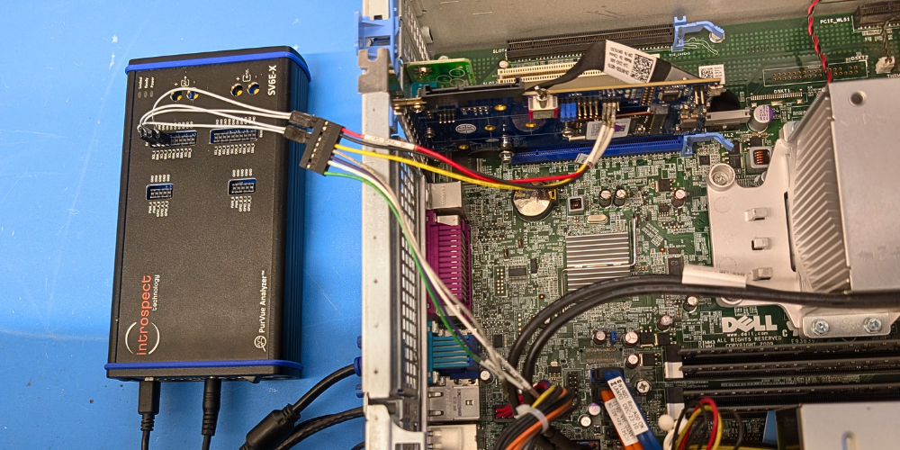
The SV6E-X Mid-Frequency Digital Test Module is Introspect’s award-winning solution for testing and validating I2C, I3C interfaces and those derived from it. Naturally, it is able to support the MCTP protocol with ease.
For example, to use the SV6E-X as a controller (primary device) and to generate MCTP messages over I3C to a managed device under test, simply use a command like:

Where the arguments in the command allow easy definition of the MCTP packet fields per the message format shown in Figure 1. Note that PEC byte is automatically computed and the user does not have to calculate it.
Similarly, the SV6E-X can act as a target (secondary device) for testing primary devices. In this case, performing a secondary to primary MCTP message transfer over I3C in IBI mode can occur with the following code example:

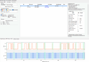
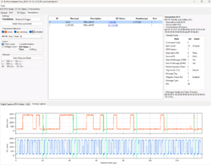
Finally, the SV6E-X can be used as a protocol analyzer and a real-time oscilloscope, and these features are all available for MCTP testing. Figures 6 and 7 are two examples of an MCTP transfer decoding with the protocol analyzer.
In this article, we described the MCTP protocol and how it is encapsulated over SMBus/I2C or the MIPI I3C protocol. We illustrated how MCTP packet bytes can be formatted to create messages from a primary device to a secondary device, and we also showed how a secondary device can send response messages back to the primary device. Finally, we introduced the SV6E-X Mid-Frequency Digital Test Module and showed how it naturally supports MCTP testing allowing ease design, debug and characterization of the MCTP device under test.

