

The common-mode performance of high-speed digital receivers is very important in mobile or mobile-influenced applications. The reason is that receivers operating in these applications are often subjected to large voltage disturbances due to ground bounce, wireless interference, and crosstalk. So, they must be tested for tolerance to common-mode noise. In this Technical Insights brief, we describe the topic of testing common-mode rejection for the MIPI Alliance® D-PHYSM specification. For this specification, in particular, the requirement of common-mode rejection testing is doubly challenging because the common-mode noise must be applied only during the high-speed (HS) portion of a data transmission and not the low-power (LP) portion.
As we will show, legacy methods for testing common-mode interference rejection for D-PHY are both extremely clumsy and just not capable of providing the necessary coverage. On the other hand, the SV5C-DPTX MIPI D-PHY Generator turns this test into a complete breeze!
The Test Requirement
In the latest D-PHY CTS specification, there are two requirements for injecting common-mode noise into a D-PHY receiver. One is to inject a common-mode sine wave interference with a frequency between 50 MHz and 450 MHz on top of a D-PHY transmission. This is referred to as DVCMRX(LF) in the MIPI specification, as shown in Figure 1.

Figure 1: MIPI specification for the common-mode interference test.
The second requirement is to inject a sine wave interference with a frequency that is much higher than 450 MHz (up to 1.33 GHz). This is referred to as DVCMRX(HF). The challenge with both tests is that the low-power (LP) mode of the D-PHY transmission needs to be untouched. This means that the noise injection needs to be enabled and disabled dynamically and with extremely stringent timing requirements that are on the order of nanoseconds. Another challenge is that it is very difficult to physically combine external interference sources on top of a low voltage swing digital transmission, especially at high data rates.
Legacy Solutions
The most common way of attempting to meet the above test requirement is to use a MIPI data generator and an external sine wave generator and then to combine their outputs. This is shown in Figure 2.

Figure 2: Legacy setup for injecting common-mode noise onto a high-speed digital test pattern.
The signal combiner is typically a lab component such as the one shown in Figure 3. As can be seen, it is a connectorized coaxial component, and this already represents a challenge. Imagine having to place such component on all four lanes and clock lane of a D-PHY link! This requires 10 such components and 30 SMA cables.
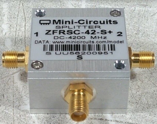
Figure 3: Example of signal combiner component used in high-speed validation laboratories.
Protocol-Aware AWG
The SV5C-DPTX MIPI Generator eliminates all of the above constraints because it integrates a protocol-aware arbitrary waveform generator (AWG). This means that it can create high-speed digital test data the way a MIPI Data Generator does, and it can simultaneously enable arbitrary interference sources – all controlled through software. In terms of hardware setup, Figure 4 shows how the SV5C-DPTX can be used to perform the tests described in this document. As can be seen, there is no requirement for any external components between the generator and the device under test.
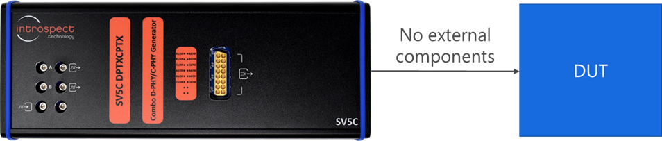
Figure 4: The SV5C-DPTX setup does not require any external components.
All controls for the common-mode interference sources are available through software. For example, Figure 5 shows a CommonModeNoise component class that allows the user to specify parameters such as noise type and noise frequency.
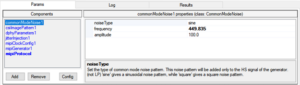
Figure 5: Software API showing common-mode noise injection parameters.
What is most compelling is that each wire in a MIPI bus gets its own fully programmable interference source. So, if you are testing a four lane D-PHY receiver, this is equivalent to 10 separate high-performance signal sources, all included inside the SV5C-DPTX! Figure 6 shows how each wire can be associated with an interference source.
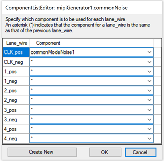
Figure 6: Every leg of every differential lane gets its own waveform generator.
The following two figures show how the common mode noise injection appears on a high-speed MIPI D-PHY data transmission. In Figure 7, we see that the first phase of the waveform (the LP phase) is clean, and then a sinusoidal waveform starts exactly when the MIPI signal transitions from the LP00 state to the HS-Zero state. Notice how the digital data still maintains its sharp edges. Figure 8 shows a zoomed-in waveform of the digital data. Signal integrity on the high-speed edges is guaranteed irrespective of the noise being applied. This is truly outstanding performance!
Finally, Figure 9 shows a persistent oscilloscope trace that illustrates the effect of noise on the high-speed signal. The intention of this figure is to again show how the signal integrity of the high-speed data is maintained.
Figure 7: Illustration of the protocol-aware control of the waveform generator.
Figure 8: Digital data maintains sharp edges even in the presence of additive common-mode noise.
Figure 9: Persistent oscilloscope display showing the effect of common-mode noise on the digital data being transmitted.
Conclusion
In this Technical Insights brief, we described the common-mode interference test requirement for MIPI D-PHY receiver applications. We showed how ineffective legacy test environments can be, and we then illustrated how the SV5C-DPTX makes this test a complete breeze. The SV5C-DPTX integrates a protocol-aware AWG that enables it to dynamically switch interference sources with very high precision. It also integrates an independent noise source for each wire of its output channels, thus offering unprecedented test coverage for this difficult test.
