This article was originally published by EE World Online. You can find the original article here.
BY
What is the MIPI I3C interface and where might I use it?
I3C improves on I2C through higher speeds and backward compatibility.
You’ll often want to interconnect two chips on a circuit board, and a standard interface can help you design efficiently. Engineers working at a division of Philips thought so back in 1982, so they developed the Inter-Integrated-Circuit interface, which they dubbed I2C. Of course, things change over the years. That Philips division has evolved into NXP Semiconductors, for example. And engineers affiliated with the MIPI Alliance, which focuses on mobile and mobile-influenced devices, decided to improve I2C with the goal of easing sensor integration. In 2016 they introduced the Improved-Inter-Integrated-Circuit specification, which they dubbed I3C (with no superscript). I3C facilitates the integration of mid-speed embedded applications that include not only sensors but also actuators, power regulators, MCUs, and FPGAs.
Where can I get the specification?
You can download it here. MIPI members can download the full version, while nonmembers can download I3C Basic.
What are some of the improvements?
Speed is one. I2C tops out at 5 Mb/s. I3C is much faster. I3C is also more power-efficient. It transmits more data using less energy per bit.
Exactly how fast is I3C?
It’s complicated. According to Matthew Schnoor, a debug architect at Intel and member of the MIPI Debug Working Group, it depends on whether you use the Standard-Data-Rate (SDR) mode or one of several High-Data-Rate (HDR) modes. Those modes include HDR-Double Data Rate (HDR-DDR), HDR Ternary Symbol Legacy (HDR-TSL), HDR-Ternary Symbol Pure (HDR-TSP), and HDR-Bulk Transport (HDR-BT). Table 1 provides effective bitrates for single-, double-, and quad-lane implementations for each mode, assuming a clock speed of 12.5 MHz.
I3C Effective Bitrates for a 12.5-MHz Clock
| I3C Mode (protocol) | Effective Bitrates (Mbps) | ||
| Single lane | Dual lane | Quad lane | |
| SDR Mode | 11.1 | 22.2 | 44.4 |
| HDR-DDR Mode | 20 | 40 | 80 |
| HDR-TSL Mode | 23.52 | n/a | n/a |
| HDR-TSP Mode | 33.33 | 50 | 100 |
| HDR-BT Mode | 24.24 | 48.48 | 96.96 |
Courtesy of the MIPI Alliance
Notes:
- HDR-ternary modes (HDR-TSP and HDR-TSL) are not included in I3C Basic
- SDR multilane transfers (dual-lane and quad-lane) are not included in I3C Basic
- HDR-DDR multilane transfers (dual-lane and quad-lane) are not included in I3C Basic
- HDR-TSL does not support any multilane transfers (this is the only HDR-ternary mode that can be used with legacy I2C devices in a mixed-bus configuration)
Dual and quad lanes: doesn’t that make I3C a parallel bus?
When describing a bus, serial and parallel apply to how the data is transmitted and received. For example, the old Centronics parallel printer interface transmitted one byte of data at a time over eight wires, with extra wires (36 in all including the data wires) for chassis and signal ground as well as strobe, busy, and reset signals, an “out of paper” warning, and so forth. With a serial interface, the data and relevant status bits are serialized at the transmitter, sent over one serial lane, and deserialized at the receiver. Think of a quad-lane I3C interface as four serial buses that happen to be in parallel.
Apart from publishing the specification, how does the MIPI Alliance support interoperability among I3C designs?
The I3C working group held a plugfest last year in Munich. Participants included Binho, Intel, Introspect Technology, Prodigy Technovations, Robert Bosch, and STMicroelectronics. The group intends to host a second I3C plugfest June 26-30 in San Jose, CA, during MIPI’s 63rd Member Meeting North America. MIPI also offers an I3C conformance test suite (CTS) designed to improve interoperability of products that use I3C.
How can I troubleshoot my I3C design?
First, contact your oscilloscope manufacturer. Keysight, Pico Technology, Teledyne LeCroy, and Tektronix all offer support for I3C debug. In addition, several participants in last year’s plugfest offer test and debug solutions for I3C. Binho offers an I3C protocol-analyzer plugin for use with the Saleae Logic line of analyzers. Introspect Technology offers I3C test and debug modules. And Prodigy Technovations offers an I3C protocol analyzer and exerciser.
What else should I know about I3C and test?
I3C itself can serve as a debug window into a device, as described in the MIPI Debug for I3C specification. That specification describes standardized methods of transporting software traces between a debug and test system—typically, a computer running debug and test applications—and a target system.
SoC engineers can use the specification to design into their chips an I3C interface that can be used for debug purposes only or that can be shared among debug and mission-mode data-communications functions. System hardware and software engineers can also use the specification to design products that can be debugged using I3C.
Will I3C replace I2C?
I3C certainly offers advantages. In addition to higher speeds and lower power consumption, I3C includes specific features such as in-band interrupts from target to controller, dynamic addressing, and a hot-join mechanism that allows slaves to join an I3C bus after a master has initialized it. Nevertheless, I2C will remain a popular low-cost solution for designers who don’t need the unique features of I3C. Also note that I3C maintains backward compatibility with I2C for most devices, so you might find that your optimal design will include both (Figure 1).
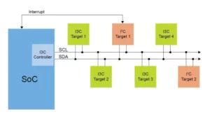
Figure 1. An I3C design can include I2C devices (Image NXP Semiconductors).